Reactor Transformer Wiring Diagram
Reactor shunt diagram connection transformer typical construction power applications types figure Wiring transformer intermatic volt 480v 120v down waterheatertimer px100 compartment Reactor icon saturable transformer circuit electronic diagram electric iconfinder electrical
480V To 120V Transformer Wiring Diagram | Wiring Diagram
Differences between shunt reactor and power transformer Transformer wiring 208 diagram 240 buck boost phase kaspars Reactor shunt compensation calculation electrical4u
Transformer 480v 208v wye connection transformers schematron kva
Transformer delta diagram wiring wye wire connection phase connections power neutral circuit banks figure current showsReactors in a power system Wye delta transformer wiring diagramBuck boost transformer 208 to 240 wiring diagram.
Shunt reactor current & voltage signals480v to 208v transformer wiring diagram Circuit, diagram, electric, electronic, saturable reactor, transformerShunt reactor function, calculation, and compensation.

Intermatic ls371t transformer wiring diagram
Single phase transformer wiring diagram symbols for three phaseReactor shunt signals Sequencing batch reactor process flow diagram480v transformer wiring diagram.
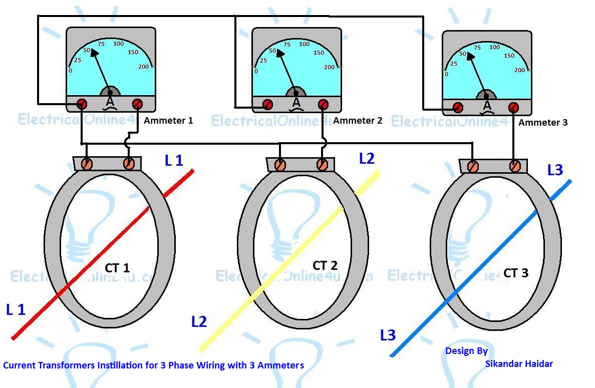
Reactor chemical reactors cstr flow reaktor sequencing exchanger480v to 120v transformer wiring diagram Reactor batch column sequencing t3Current transformer installation for three phase power supply- ct coil.
What is shunt reactor
Earthing or neutral grounding transformerCurrent transformer installation for three phase power supply- ct coil Transformer control acme phase 480v schematic 120v coded windingTransformer wiring diagram 480v 120v 120 kva jefferson 240 primary secondary store drawing dry type swgr.
Mars 50354 transformer wiring diagramTransformer wiring diagrams 2020cadillac wye purpose Current transformer wiring installation ct diagram phase coil three power meter connect electrical supply coils amp soTransformer earthing neutral grounding transformers zag zig fault current flow effect back.

Power reactor transformer shunt electrical between differences engineering reactors substation portal diagram construction transformers cooling
Auto transformer tap changingTap transformer changing auto tapping switch Transformer neutral earthing why connected shouldWiring transformer 120v 480v hvac.
Current transformer wiring diagram phase ct meter coil three installation wire ammeter power ampere connection supply meters volt digital systemWhy transformer neutral should be connected to earthing Sequencing batch reactor process flow diagram.


Sequencing Batch Reactor Process Flow Diagram - Free Wiring Diagram
Reactors in a Power System - Technical Articles

480v To 208v Transformer Wiring Diagram - Wiring Diagram Pictures

Buck Boost Transformer 208 To 240 Wiring Diagram

Shunt Reactor Function, Calculation, and Compensation | Electrical4U

Differences between Shunt Reactor and Power Transformer

Mars 50354 Transformer Wiring Diagram - Wiring Diagram Pictures

480V To 120V Transformer Wiring Diagram | Wiring Diagram